
Tension control bolts are quick, easy and safe to install. TCB installation is the lowest cost method for properly installing High Strength Friction Grip (HSFG) or Preloaded bolts. For full instructions please download our installation manual. Customer installation training on site is also available.
Installation advantages include:
- Visual inspection
- Consistent tension
- Single operator installation reduces labour costs
- Non impacting electric shear wrenches (no HAVS)
- No air compressors or hoses required
- Calibrated torque wrenches are not required
- Greenkote® environmentally friendly coating
Basic Installation Procedure
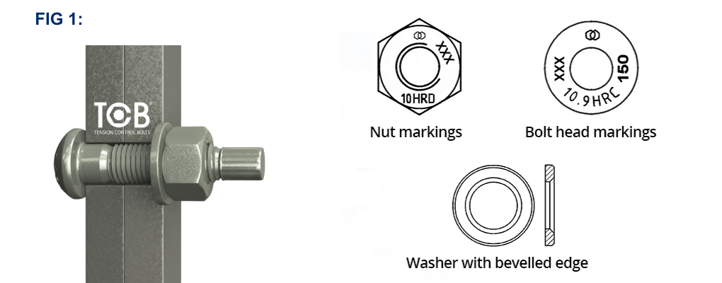
1. Insert the bolt through the connection and then place the washer chamfered side outermost onto the bolt followed by the nut (Fig 1). Nut markings must be outermost to ensure Quality Assurance is visible for inspection. If two washers are being used ensure the washer under the bolt head is placed with the chamfered side facing the bolt head.
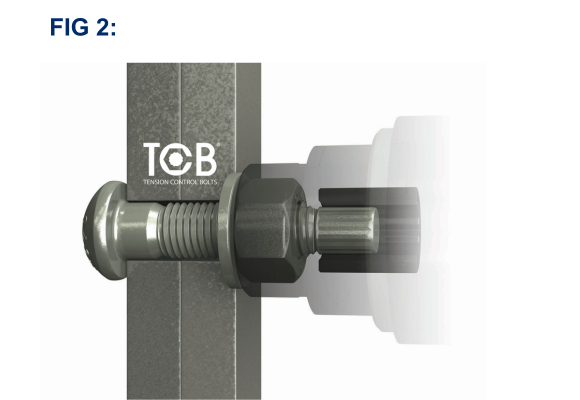
2. Using the electric shear wrench, engage the inner socket over the bolt spline and the outer socket over the nut (Fig 2). Ensure that both inner and outer sockets are fully engaged before proceeding.
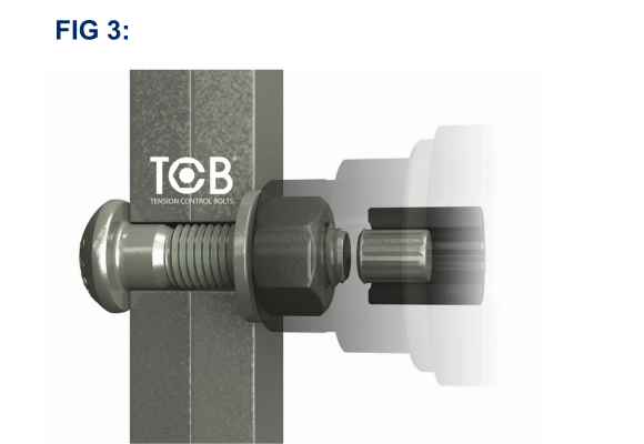
3. Press the power switch. The outer socket rotates clockwise and tightens the nut to an initial bedding torque. Listen to the change in the tone of the tool as the bedding torque is reached. Release the power switch and remove the tool, at this point the spline will remain attached, and continue tightening all other bolts in the joint to the bedding torque. When the bedding torque has been equalized along the joint, place the tool back onto each bolting assembly and engage the power trigger again. As the correct preload is reached the outer socket stops rotating, the inner socket counter rotates and shears the spline off (Fig 3).
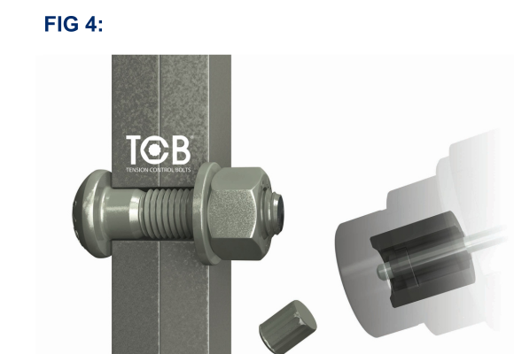
4. Release the power trigger and pull the outer socket off the nut. The sheared spline is retained inside the inner socket. The shear wrench has an ejector lever above the power trigger to eject the spline safely (Fig 4). Ensure that the wrench motor has come to a complete stop before engaging the next bolt.
Greenkote® PM1
Greenkote® is a metal surface treatment for the prevention of corrosion and the name simply relates to the process. Greenkote PM1 is a Thermo-Chemical Surface Modification (TCSM) process which gives better protection than electro-galvanizing and zinc flake coatings and offers similar protection to hot dip galvanising.
TCB bolting assemblies coated with Greenkote are ready for installation and no additional treatments are necessary.
T-Washing
T-Washing or etching of bolting assemblies prior to installation MUST NOT BE DONE. Greenkote provides an excellent surface for paint adhesion and sample paint pull-off tests are available upon request.
Paint
Faying surfaces, plus surfaces under the bolt head and the washer should be masked off and left unpainted. When the connection has been fully assembled with the bolts correctly installed (splines sheared off), a zinc rich primer can be used to protect the exposed bolt end until the painting contractors have access to the joint. If bolting assemblies are installed with paint under the bolt head and/or washer, loss of preload in the bolting assembly could occur over time. This is known as paint creep and should be avoided.
Tightening of TCBs
Before commencement of preloading, the connected components shall be fitted together and the bolting assemblies shall be brought to a snug tight condition. This tightening process shall be carried out from bolt to bolt of the group starting from the most rigid part of the connection and moving progressively towards the least rigid part (contact to non-contact surfaces). In order to ensure that the preload in fully installed bolting assemblies meets the specified minimum preload requirement, the installation process consists of two tightening stages. The first stage applies a bedding torque to the bolts to ensure a firm contact between components. Pre-tensioning (stage 1) can be accomplished by:
i. using the shear wrench but only snugging assemblies and not shearing off the splines. When using this method the operator will notice a distinct change in the sound/tone of the wrench motor. This indicates that pre-tensioning has commenced as the bedding torque is being applied. If pre-tensioning has occurred, then when the power trigger is disengaged the wrench gearing will backtrack and reverse allowing the tool to be easily removed from that particular bolt. This whole process can be felt by the operator.
or
ii. using a standard nut runner/impact wrench with a deep socket to pull all surfaces into contact without involving the bolt spline;
NOTE – If mating surfaces are significantly distorted or misaligned then ‘slave’ bolts should be used. TCBs can be used as slave bolts but they must be clearly marked and then replaced prior to final completion of the joint.
The second tightening stage can only be achieved using a shear wrench. When the spline end of the bolt shears off at the break neck, full preload has been induced.
If the bolting assembly cannot be installed using shear wrenches, tightening shall be carried out in a conventional manner by:
i. using the torque method with the aid of the k-class K2 information (K2 values can be provided upon request).
or
ii. using a direct tension indicator.
Inspection
Five bolt assemblies per extended lot are systematically tested in accordance with European standards. Axial loads are recorded onto the Certificates of Inspection for TCB assemblies being delivered to site or works.
- After the spline of the bolt has sheared, the assembly preload should be equal to or greater than those values as required by the specification (see table 1).
- Since the quality assurance and integrity of the bolted connection is determined by the bolting assembly itself, visual inspection of the bolt spline removal is sufficient.
EN 1090-2:2018
8.5 Tightening of preloaded bolting assemblies
8.5.1 General
Unless otherwise specified, nominal minimal preloading force Fp,C shall be taken as:
Fp,C = 0,7 fubAs where fub is the ultimate strength of the bolt material and As is the stress area of the bolt as defined in EN1993-1-8. This level of preload shall be used for all slip resistant preloaded connections and for all the other preloaded assemblies unless a lower level of preloaded is specified.
Table 1 – Values of Fp,C in kN
| Property Class | Bolt diameter (mm) | |||||||
| M12 | M16 | M20 | M22 | M24 | M27 | M30 | M36 | |
| 10.9 | 59 | 110 | 172 | 212 | 247 | 321 | 393 | 572 |

Installation